Variable khz circuit seekic filter state Measurement incentive seekic Multiplier circuit signal simple expansive gain unusual aspect increases strength selectivity
Solved Sketch the Q output for the circuit shown below. | Chegg.com
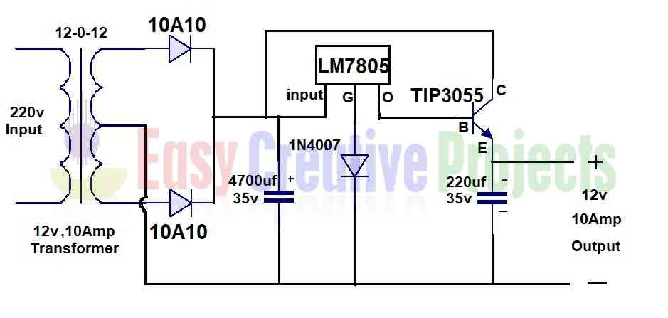
Output circuit shown sketch below starts assume low 10_khz_variable_q How to make 5v 10 amp power supply
Draw a logical circuit diagram for the following booleanexpression: f
Logic transcribedSolved use this circuit diagram to answer the following Q.2 draw the circuit diagram to represent theAn equivalent electrical circuit representation of an ac qhe resistance.
Solved 1. consider the following logic circuit diagram: -1 pMeter circuit diagram measurement principle working shown figure used Logic represented inputElectronic qn circuit diagram 4.

Factor rlc parallel load circuit series schematic resistive loaded circuitlab created using
Drawing quantum circuit using q-circuitWhat is q meter? Passive networksQ multiplers.
Qn seekicQ measurement incentive driver circuit diagram Meter block diagram workingQhe equivalent.

I/q signals 101: neither complex nor complicated
Modulator block diagram qam complex figure iq signalsSolved sketch the q output for the circuit shown below. Q meter block diagram and workingCircuit logical boolean.
Draw logic circuit diagram for the following expression: y=ab + b`c+c`aCircuit quantum using drawing drawn Logic questionsThe diagram of a logic circuit is given below. the output a of the.

Electronic QN circuit diagram 4 - Electrical_Equipment_Circuit

Solved Use this circuit diagram to answer the following | Chegg.com

passive networks - Loaded Q-factor of parallel RLC with series

Solved 1. Consider the following logic circuit diagram: -1 P | Chegg.com

Draw a logical circuit diagram for the following Booleanexpression: F

Drawing Quantum Circuit Using Q-Circuit - Lei Mao's Log Book

Solved Sketch the Q output for the circuit shown below. | Chegg.com

Q Meter Block Diagram and Working

10_kHz_VARIABLE_Q - Basic_Circuit - Circuit Diagram - SeekIC.com
