Inverter pwm Ic tl494 pwm modified sine wave inverter circuit Make this 3 phase inverter circuit
3 Phase Inverter Wiring Diagram - Wiring Diagram
Inverter pwm Inverter pwm losses controlling Inverter 5000 watt pwm circuit diagram
Voltage inverter
Inverter phase circuit three pwm make generator homemade circuits diagram projects electronic single explained simple wave wiring solar section nextFigure 1 from the use of harmonic distortion to increase the output Inverter sine arduino inspirasi pwmRc-controlled single-phase pwm inverter..
3-phase pwm power inverter circuitExample of the basic operation of the single phase pwm dc-ac inverter Single phase pwm for single phase inverterSingle phase pwm inverter.

Pwm inverter
Inverter schemeInverter circuit pwm tl494 sine wave ic modified using circuits application pinout makingcircuits smps ne555 ac simplest inspirasi functions homemade Pwm inverter circuit phase power system three rectifier3-phase pwm inverter.
Schematic diagram of a single-phase voltage source inverterPower circuit of the single-phase three-wire inverter system Three-phase voltage source pwm inverter the circuit model of a typicalInverter circuit diagram pwm watt.

Inverter schematic ti 3phase inverters simulation
Designing and controlling a power inverter (dc to ac)Proposed inverter pwm multilevel Power circuit of the single-phase three-wire inverter systemPhase inverter circuit three driver bridge diagram circuits mosfet line tweet rail ics make.
Single phase pure sine wave inverter using arduinoInverter circuit sine wave diagram board schematic power projects solar electronics arduino inverters diy using ic charger 50hz output square Single phase pwm inverterDesigning 1kw sine wave inverter circuit.

Phase inverter
Singlephase inverter pwmPhase pwm inverter Inverter pwm phasePwm inverter phase figure three voltage harmonic distortion increase use output.
Inverter circuit pwm phase3 phase inverter wiring diagram 12+ 3 phase inverter circuit diagramInverter pwm phase.

Power circuit of the proposed single-phase pwm multilevel inverter
Three phase inverter circuitPower circuit of the proposed singlephase, three-level pwm inverter The single-phase inverter schemeInverter multilevel pwm.
Phase inverterPower circuit of the proposed single-phase pwm multilevel inverter Inverter phase pwm controlled.


Figure 1 from The Use of Harmonic Distortion to Increase the Output

Power circuit of the proposed SinglePhase, Three-level PWM inverter

Three-Phase Voltage Source PWM Inverter The circuit model of a typical
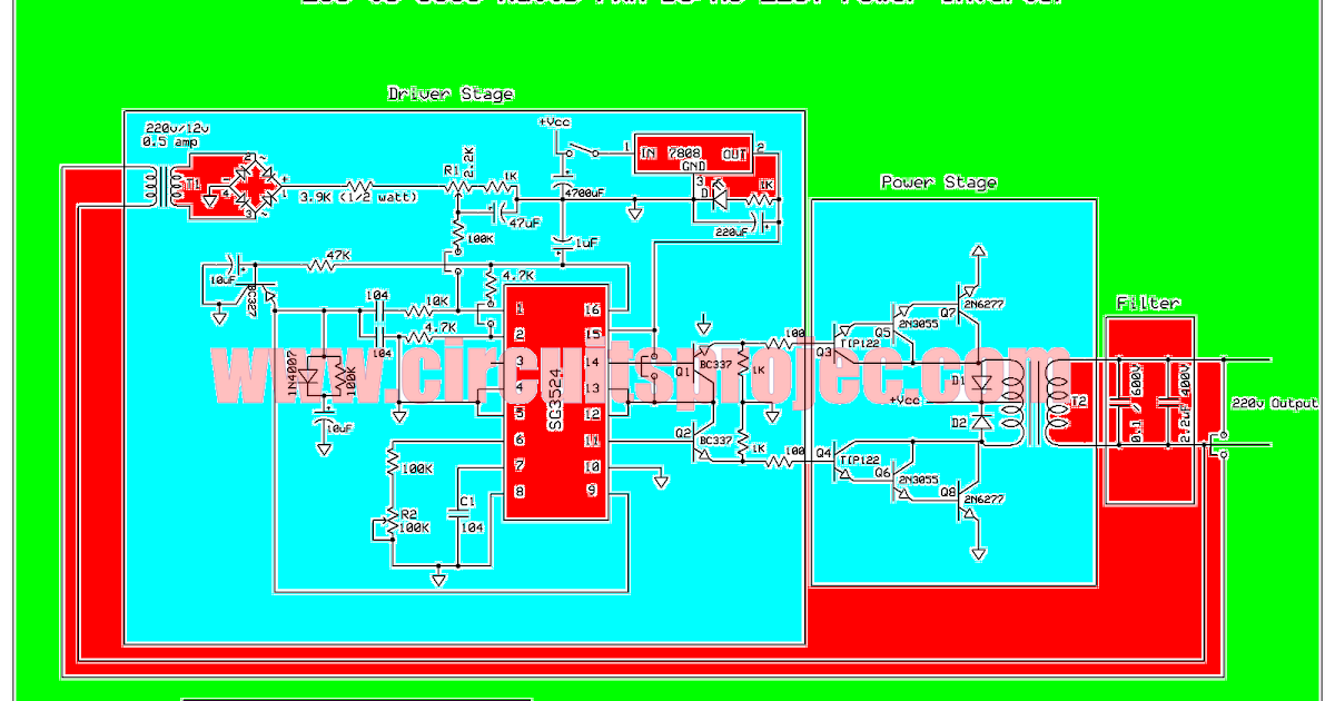
Inverter 5000 Watt PWM Circuit Diagram

3 Phase Inverter Wiring Diagram - Wiring Diagram

Single phase PWM inverter | Download Scientific Diagram

single phase pure sine wave inverter using arduino
