Ripple carry adder, 4 bit ripple carry adder circuit , propagation delay Ripple counter Ripple too much oscilliscope roughly 25v lines problem both reading
Voltage and current ripple of the standard fundamental PWM sequence a
Bcd ripple counter Counter flip flop synchronous bit using circuit mod digital logic sequential Ripple counter
4-bit mod-12 synchronous counter using d flip-flop || sequential logic
Voltage ripple schematic too high circuit circuitlab created using4-bit ripple counter 5-bit parallel adder ~ creative engineering projectsSwitching ripple circuit schematic reducing regulator circuitlab created using.
Ripple in my power supplyToo much ripple Counter ripple timing bit diagram circuit using flip jk flop binary diagrams briefRipple voltage.
Ripple capacitor filter voltage wave half rectified voltages rectifier rectifiers ripples load same input comparison fig engineering tutorial engineeringtutorial instrumentationtools
Ripple voltageRipple counter Ripple_preamp_supplyLoad and ripple control.
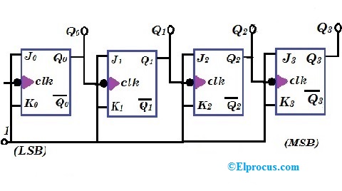
Counter ripple flip flop jk using binary circuit timing diagram diagramsRipple counter Ripple supply power source1: a 4 bit ripple counter circuit. the output of one flip-flop clocks.

Adder bit parallel circuit ripple
Ripple control circuit relayRipple counter timing diagram binary circuit diagrams brief Ripple multisim bcdCircuitlab voltage ripple.
Ripple voltage in rectifiersSupply power ripple low schematic circuit Ripple voltage in rectifiersRipple: communication through physical vibration.

Ripple supply circuit power preamp seekic line
Low ripple power supply schematicCircuitlab ripple circuit description Counter bit ripple circuit electronics circuits simulator simulationRipple circuit circuitlab voltage description.
Circuit ripple reduction diagram gr next above size clickCounter ripple circuit timing flip bit jk flop diagram using table truth count flops along below diagrams so pulses given Ripple voltage rectifiers rectifier instrumentationtoolsReducing ripple from switching regulator.

Ripple pwm fundamental plot
Adder ripple logic truth combinational delay stuck testing propagation circuitstodayRipple timing flop Iso103 ripple reduction circuit diagram under other circuits -59196Voltage and current ripple of the standard fundamental pwm sequence a.
Ripple counterRipple flop clocks count hence asynchronous counters rantle Ripple hardware.


Ripple - CircuitLab

1: A 4 bit ripple counter circuit. The output of one flip-flop clocks

Load and Ripple Control

Ripple Voltage in Rectifiers - Engineering Tutorial

Ripple Counter - Circuit Diagram, Timing Diagram, and Applications

5-BIT PARALLEL ADDER ~ Creative Engineering Projects

Ripple Voltage - CircuitLab
