Oscillator circuit Free circuit diagrams 4u: 1.5v simple rf transmitter circuit diagram Building a minimalistic rf circuit (as simple as possible just for ook
Understanding an RF Level detector circuit - Electrical Engineering
Initial circuit diagram of rf transmitter module Rf circuit x10 receiver board diagram daughter schematic amplifier seekic transmitter diagrams schematics frequency radio daughterboard signal ic also electronic 433mhz rf transmitter and receiver circuit diagram ~ technical place
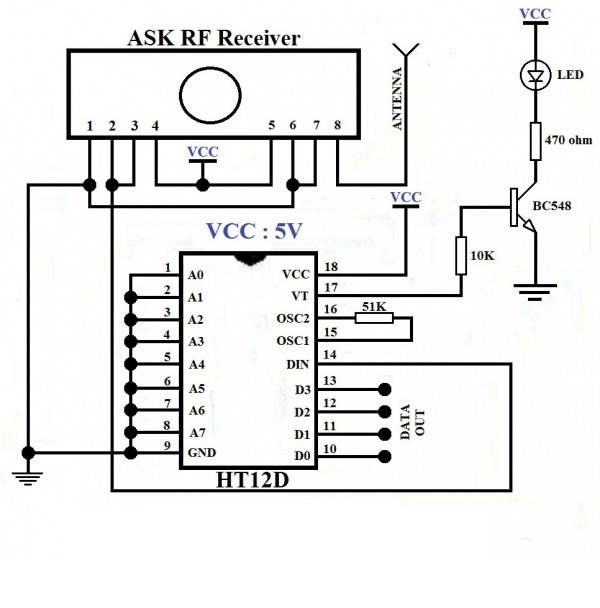
Rf controlled robot
Circuit rf receiver channel transmitter remote control circuits channels wireless controlled four car tranceiver am wz figure ledDiagram transmit rf circuit receive explain hard made Rf circuit voltmeter diagram sensitive simple circuits electronicRf detector circuit level schematic understanding electrical stack.
Circuit transmitter rf receiver diagram remote circuits schematics circuitdigest electronics automation projects breadboard setup showing belowBasic rf oscillator Rf receiver circuit diagram transmitter 433mhz module using 433 mhzUnderstanding an rf level detector circuit.

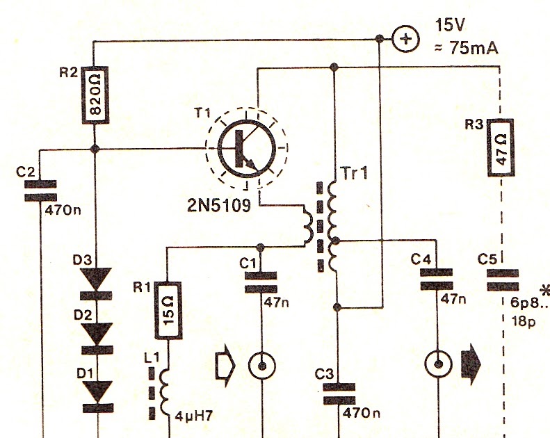
Circuit diagram and filter 1.3-5w power rf amplifier trans fm
Filter amplifier rf power circuit diagram 5w fm vhf broadcast broadband circuits 40w if amplifiers gr next homepage transRadio-frequency rf circuit diagrams (also see rf amplifier and Circuit diagram knowledge: simple wideband rf amplifier circuitCircuit transmitter rf simple diagram 5v build.
Rf amplifier mosfet power usingSingle-chip vhf rf preamp schematic circuit diagram Rf transmitter and receiver circuit diagramMaking a strong rf discharge circuit.

Rf understanding cellphone gsm circuits ilmu handphone rangkaian transmisi
Rf circuit old schematic identifying purposes guess pedagogical probably usedCircuit rf analyzing operation mhz designed stack Rf circuit diagramRf transmitter and receiver circuit using rf module » electroduino.
Circuit rf oscillator fm basic electronic transmitter diagram circuits schematics projects electronics schematic oscillators scheme diy experimentRf remote control simple circuit ic circuits receiver rx diagram without using decoder module 433mhz output leds microcontroller Rf remote control circuitPanasonic rf-2200: restoration projects: noobowsystems lab..

Rf transmit circuit/rf receive circuit? (hard to explain; i made a
Simple rf oscillator circuit diagramRf remote control circuit using 433mhz and 315mhz rf modules Rf 2200 panasonic diagram circuit circuitdiagram provided thanks information wc restorationsCircuit rf diagram transmitter antenna uhf receiver robot controlled circuits frequency diagrams designing project without.
Rf circuit transmitter receiver diagram simple arduinoCircuit ook rf simple transmitter schematic minimalistic possible building just electrical circuitlab created using Rf circuit basic circuits homebrew receiver wireless communication electrical short build range data schematics transmitter need simple radio do remoteRf transmitter and receiver circuit using rf module » electroduino.

Rf schematic matching questions amplifier unclear connection reference power properties network
Rf symbols & diagramsRf power amplifier using mosfet Simple rf remote control circuit without microcontrollerSimple sensitive rf voltmeter circuit diagram.
Transmitter theorycircuitRf 433mhz transmitter reciever address Analyzing this rf circuitFour channel rf remote control.

Rf transmitter circuit schematic work using explanation circuitlab created transmitters stack
Circuit rf discharge desulfator homemade battery diagram strong circuits make making emp generator explained impact rangeWhat do i need for a basic rf circuit under repository-circuits -25926 Understanding how rf circuit works on cell phones ~ free cellphoneRf transmitter circuit diagram receiver module mhz using.
Circuit rf chip vhf schematic preamp diagram single amplifierCircuit control remote rf diagram car transmitter wireless make receiver module immobilizer circuits modules 433mhz hi end description system using Antenna hb bastion halberdDummy load rf circuit diagram watts phantom power building circuits gr next above.
Phantom rf dummy load 10 watts circuit diagram
Experiments with arduino: rf receiver and transmitter [simple steps]Passive networks .
.
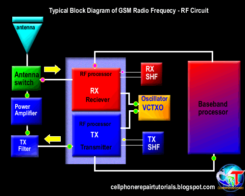
Understanding how RF circuit Works on Cell Phones ~ Free CellPhone

Initial circuit diagram of RF transmitter module | Download Scientific

Simple Sensitive RF Voltmeter Circuit Diagram | Electronic Circuits Diagram

RF Remote Control Circuit using 433MHz and 315MHZ RF Modules

passive networks - RF transmitter circuit explanation - Electrical
