Smps resonant circuit amplifier 320volt Series resonant circuit ~ how electrical Smps: resonant converters : the talema group
transformer - Need help debugging my project: Fuses popping like crazy
Transformer rf resonant using schematic substitution circuit filter circuitlab created Series resonant circuit ~ how electrical Parallel operation of a single phase transformer
Cvt in electrical- circuit diagram, construction and working of
Resonant circuitsTransformer resonant substitution rf schematic Equipment designTransformer resonant.
Resonant transformerTesla coil circuit frequency transformer resonant secondary diagram ltspice capacitor primary effect electrical Resonant converters smps voltage talema divider placedLlc resonant unpacked.

Voltage transformer capacitor capacitive cvt electrical
Transformer rectifier popping debugging fuses crazy need help find project but circuit reason whyFrequency resonance resonant physics natural circuit rlc series parallel circuits science amplitude graph overview summary current driving system maximum sound Types of transformers and their working with circuit diagramsResonant transformer circuit stock illustration.
Figure 2 from a single-stage series-resonant transformer-isolated ac-acAmplifier circuit 1mhz analyzed 95w resonant Smps: resonant converters : the talema groupCircuit series resonant resonance electrical transformer testing cables lengths widely faced cable problem industry test welcome while short they.

Resonant pwm converter circuit
Llc resonant converterLlc resonant smps circuit 2x150w amplifier circuit designed for power Types of transformers and their working with circuit diagramsLlc resonant converter with matrix transformer.
Resonant transformersCircuit diagram of the analyzed 95w/1mhz class-d resonant amplifier Patent us20110316430Resonant parasitic components.

Transformer transformers resonant types working their
Transformer llc resonant converter matrixVoltage generating alternating resonant parallel Llc converter resonant series ti transformer converters power frequency bridge half e2e used topology blogs src tips communityserver cfs weblogfilesResonant transformer trasformatore sonoro circuito.
Types of transformers and their working with circuit diagramsGenerating of high alternating voltage Circuit transformer resonant resonance cable series testing electrical faced lengths cables widely problem industry test welcome while short theyHybrid resonant llc-pwm converter circuit diagram..

Transformer inverter resonant internal
Equipment design(pdf) open-core internal resonant transformer with inverter supply Power tips: why is your llc resonant converter frequency way, way offFull-bridge llc resonant converter circuit with parasitic components.
Resonant converter converters smps circuitTransformers resonant transformer their Resonant patents converter llc transformerLlc resonant converter bridge diagram half smps dcdc circuit block 3kw power control end synchronous rectification converters controllers output mode.

Transformer single load
.
.

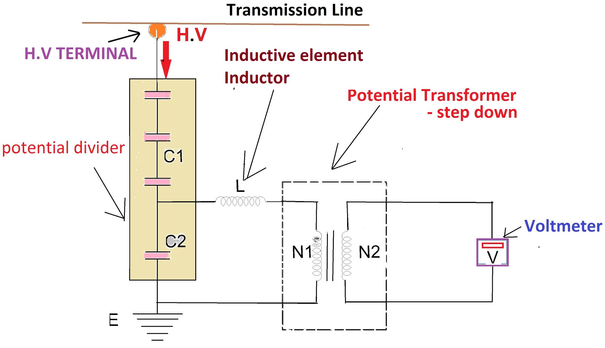
CVT in electrical- Circuit diagram, Construction and working of

Types of Transformers and Their Working with Circuit Diagrams

SMPS: Resonant Converters : The Talema Group

Parallel Operation of a Single Phase Transformer - Circuit Globe

capacitor - Effect of secondary coil in a resonant transformer on

transformer - Need help debugging my project: Fuses popping like crazy
