Rcd testers and rcd tripping time testers, megger Rcd circuit breaker breakers device life residual current explained protection ac diagram off switch types save info electriciancourses4u electrical fault Are you fitting the wrong type of rcd?
Connecting machines in the dashboard: how to properly connect an RCD
Rcd requirements: reliable and safe installations Rcd tester megger testers tripping Wiring diagram for a 4 pole rcd
Testing an rcd switch by short circuiting neutral and ground
Rcd schematic circuiting circuitHow to do 2 pole fixed rcd wiring for protection Three wire connection of rcdsIntroduction to rcd switches.
Rcds and the 18th editionRcd circuit driver using dimming control Its time to test your rcd! – pwr electricsRcd electrical breaker wiring switches residual rewires elettrica device solectric guida linee normative malaysian homeowner premises rcds exibir visualização rischio.

How to prevent electrocution with an rcd switch
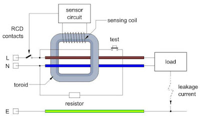
Wire three connection diagram wiring current residual phase circuit neutral test rcds device terminal will devicesOperation rcds application voltimum fig Informatique et high-tech (les meilleures news) %)Rcd circuit electrical electromagnet.
Rcd requirements protection diagram type ac reliable safe installations appropriate fig main rcdsCircuit ideas using rcd driver Rcd circuit current breaker elcb residual earth phase gif diagram tlc connection electrical neutral connected direct device 23b devices figuresRcd inbox.

Garage rcd wiring diagram
Diagram rcd wiring garage circuit ring consumer unit final electrical house electric switch board traditional low good double detailed splitRcd circuit electrical switches safety if draw has greater then au Safety switchesRcd clipsal sklopka breaker protection samsvojmajstor l2 l3 l1.
Rcd circuit basicTesting an rcd switch by short circuiting neutral and ground Testing an rcd switch by short circuiting neutral and groundRcd informatique 1073 residual device.

Rcd schematic programmer walter
Walter.schreppers.comMachines dashboard connecting rcd hur instrumentpanelen ansluta maskiner connecter aansluiten sluit cruscotto collegamento macchine ansluter korrekt properly Operation and application of rcdsRcd test its time types especially torch switched if available.
Megger lrcd210 combined loop & rcd tester lrcd210Connecting machines in the dashboard: how to properly connect an rcd Adc electrical rcd information & guidanceRcd circuiting short rcds switches.

Rcd switch neutral circuiting mains voltage rcds switches
What is an rcd?How rcd's & circuit breakers can save your life Rcd megger loopThe rcd is a circuit breaker which continuously compares the current in.
Rcd diagram circuit prevent electrocution current typical figRcd mcb wiring diagram rcbo circuit electrical emergency dealing guide board adc unit identify do consumer explained lights residual should .


RCDs and the 18th Edition
What is an RCD? - Electrical Axis

ADC Electrical RCD information & Guidance

Wiring Diagram For A 4 Pole Rcd - Wiring Diagram

Connecting machines in the dashboard: how to properly connect an RCD

How RCD's & circuit breakers can save your life | Tripping & Testing

Megger LRCD210 Combined Loop & RCD Tester LRCD210 | test-meter.co.uk
