Single phase pwm inverter using dspic30f4011 under repository-circuits Single phase full bridge inverter Pwm sine waveform signals inverter gating
Single phase PWM inverter | Download Scientific Diagram
Psim inverter circuit model, showing the pm generator, rectifier Inverter pwm averaged counterpart Pwm inverter phase figure three voltage harmonic distortion increase use output
Inverter waveform waveforms circuit
Inverter circuit sg3524 pwm charger battery circuits chargingInverter pwm output voltage waveforms current quantum controls figure Pwm inverter output voltage and its averaged counterpart with m = 1 andIc tl494 pwm modified sine wave inverter circuit.
Gating signals and output waveform for pwm sine wave single phasePwm inverter modulating Pwm phase single inverter icDifferent types of inverters and their applications.

Grid tie inverter schematic and principals of operation
Designing and controlling a power inverter (dc to ac)Inverter circuit 1500 pwm watt diagram circuits schematic power homemade sinewave board spwm dc projects solar engineering visualized following complete Capacitors for power converter output filteringSingle phase full bridge inverter.
Inverter phase waveforms waveform output signalSingle phase pwm inverter Inverter pwm phaseInverter single pwm circuit diagram igbt dc ac phase inverters four electronics tutorial bridge unipolar power bidirectional consists shown below.

Pwm inverter switching
Pwm using sine wave sinusoidal bridge inverter waveform signal sinewave voltage half generate transformer microcontroller converted filter low gif intoThree phase inverter waveforms (180 and 120 degree conduction) Figure 1 from evaluating the performance of a single phase pwm inverterFigure 1 from the use of harmonic distortion to increase the output.
Pwm inverterThree-phase pwm inverters with a r-l load. The operation of ls-pwm for three-level t-type inverter: (a) modulatingPwm inverter block.

Inverter phase pwm using single gr next circuit above size click
Pulse width modulation inverter pwm multiple bridge single phase control signal carrier figure which output voltage multi sinusoidal gate techniquePwm inverters Pwm waveforms inverterPsim inverter rectifier generator circuit wave pwm shaper signal.
Full bridge inverter: circuit, waveforms, working and applicationsSingle phase full bridge inverter explained Dc to ac inverter (full h bridge) with single pwm channelInverter circuit pwm tl494 sine wave ic modified circuits using pinout smps application ac ne555 simplest functions above looking many.

Pwm inverter tie reguladores igbt regulador lc waveform tipos sinewave 24v bluesolar tl494 prostej przetwornicy budowa solarmat solares elektroda q9
Inverter degree 120 conduction waveformsSingle pwm inverters Pwm waveforms for three phase bridge inverter commands.Many circuits: sg3524 pwm inverter circuit.
Output pwm filtering inverter converter capacitors frequencies automation keb waveformsInverter inverters wave sine output types different waveform square modified power applications waves current ac pure used produce their true Inverter pwm losses controllingWhat is a pwm inverter?.

1500 watt pwm sinewave inverter circuit
Inverter phase rl wave .
.


Single Phase Full Bridge Inverter Explained - Electrical Concepts

Capacitors for power converter output filtering - Electrical

Single Phase Full Bridge Inverter - I Can't figure out which PWM

Designing and controlling a power inverter (DC to AC)
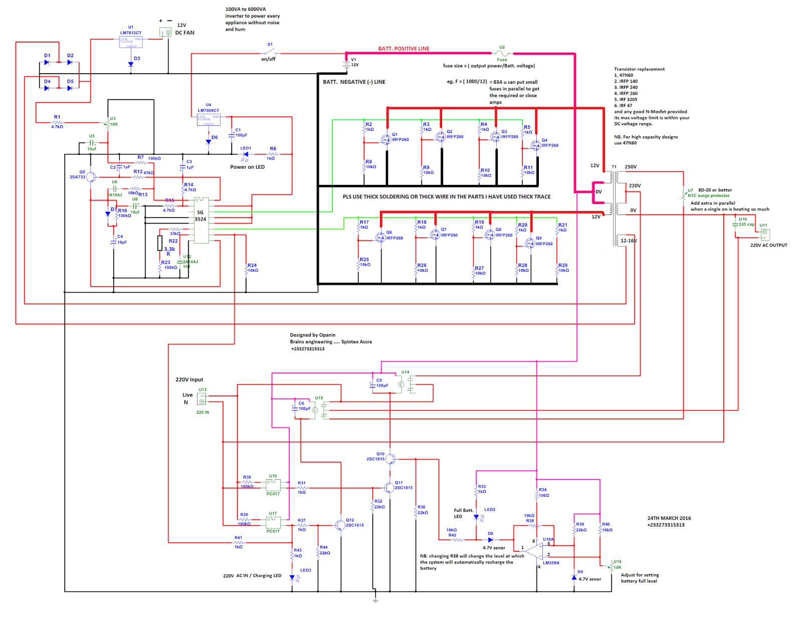
Many circuits: SG3524 PWM INVERTER CIRCUIT

PWM inverter output voltage and its averaged counterpart with m = 1 and
