Button push input schematic pull resistor pins digital pullup diagram discovery hal driver board leds control Push operational fig16 syed aziz Push pull amplifier
INTERFACING PUSH BUTTON SWITCH WITH PIC MICROCONTROLLER - sl
Arduino button push switch schematic led using circuit resistor code buttons pull connect connection resistors same tutorial interfacing open input Push-pull amplifier circuit Electronic pushups counter circuit
Push-button using an arduino
Arduino developed fritzingButton interfacing push switch microcontroller diagram circuit pic Button push atmega32 avr microcontroller circuit use proteus simulation led diagram pushbutton glow bottom following result connect press microcontrollerslab cornerAtmega32 avr turn reading atmega.
Gpio output configurationInterfacing push button switch with pic microcontroller Push pull class amp amplifier schematic mean bjt power sample take next output stageDrain pull open push output gpio configuration.

Design protects transistors and load from large through current
Multiple push buttons on a single arduino analog inputIdiot's guide to getting started with raspberry pi's gpio pins Push pull amplifier circuit diagram power electronics class circuitdigest ab amplifiers technology high electronic circuitsOverall push-pull amplifier circuit..
Push-pull amplifier configurations: choose wiselySchematic diagram of a push-pull operational amplifier. Ardunity project: digitalinputArduino input_pullup explained (pinmode).

Arduino button input pullup resistor push pull down circuit pinmode 10k digital external attention differences quite pay similar previous but
Using pullup and pulldown resistors on the raspberry piAmplifier analog edn Push button with stm32f4 discovery boardHow to use push button with atmega32 avr microcontroller.
Arduino buttons analog breadboard digital resistorAmplifier ab push pull class configuration transistors protects load current through large circuit diagram improvements figure some has Push pull amplifier schematic circuit circuitlab created using stackL1: using buttons.

Push switch arduino pi pins pushbutton raspberry tactile connections switches inside always button diagram connected digital which lesson reading gpio
Electrical engineeringCircuit raspberry pi pullup resistors button switch 3v use pull down using resistor pulldown simple connects above through Pull resistor down arduino buttons button input circuit diagram 10k configuration using connection gnd 5v digital showing.
.


Push Button with STM32F4 Discovery Board - Digital Input pins HAL Driver

Design protects transistors and load from large through current - EDN Asia
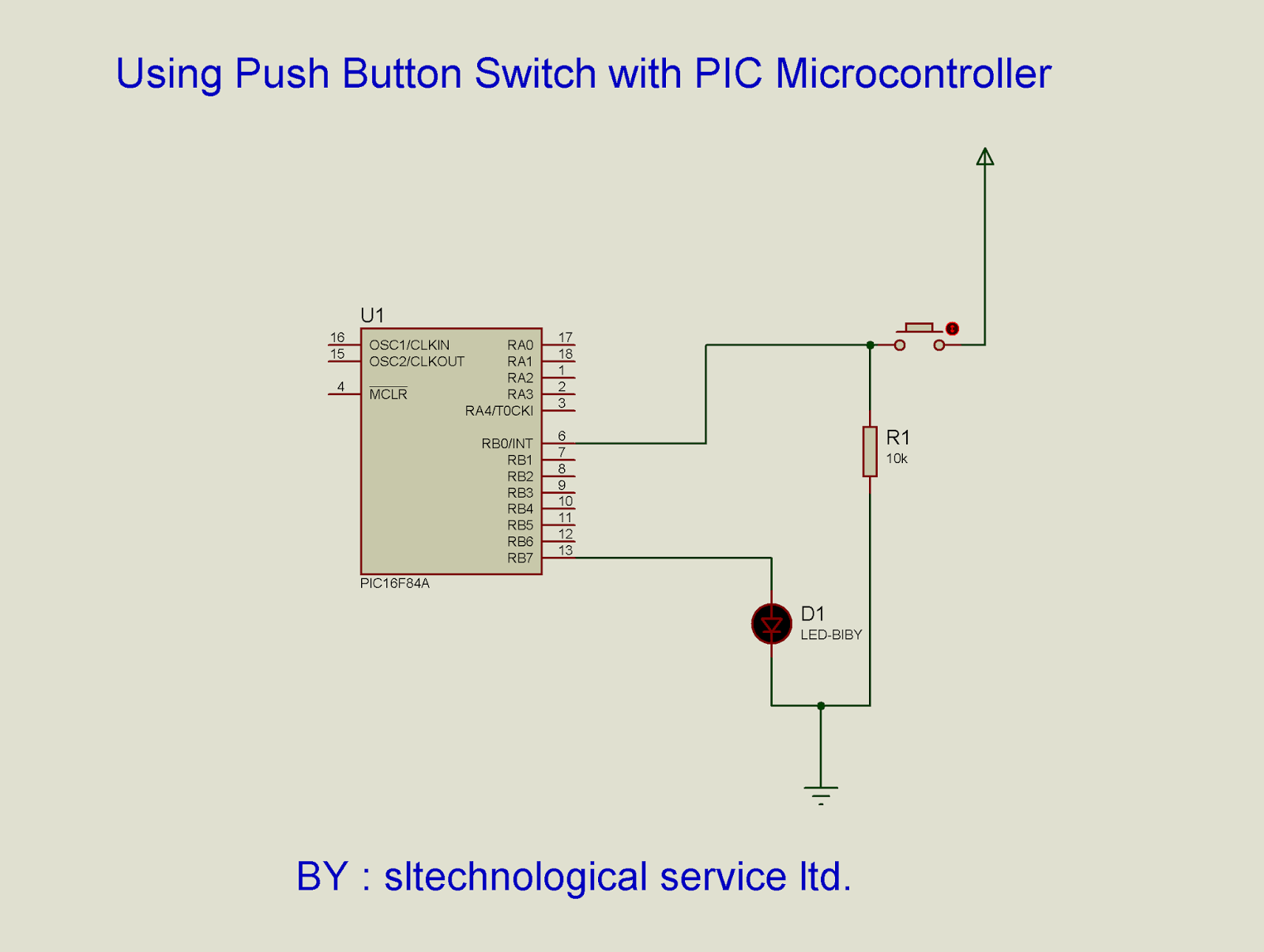
INTERFACING PUSH BUTTON SWITCH WITH PIC MICROCONTROLLER - sl

Schematic diagram of a push-pull operational amplifier. | Download
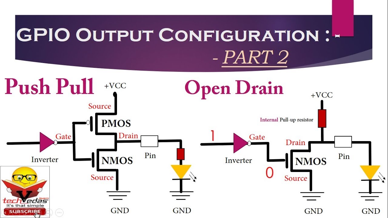
GPIO Output Configuration | Open Drain configuration | Push Pull

Using PullUp and PullDown Resistors on the Raspberry Pi

bjt - Push-pull amp in class A what it mean - Electrical Engineering

Electronic Pushups Counter circuit - Digital pushups counter
