Inductive waveform phasor purely compressor consumed explain Phasor inductive transformer capacitive Transformer loading and on-load phasor diagrams
Phasor diagram for SG operating under inductive load The expression of
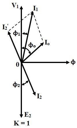
Transformer with lagging power factor load Phasor diagram of induction motor Phasor purely inductive
Phasor diagram for sg operating under inductive load the expression of
Elect principles inductive phasorPhasor transformer inductive Phasor diagram of a synchronous generatorInductive purely phasor.
Phasor laggingLeading and lagging loads Phasor load inductive power lagging leading diagram systems electric diagrams figWhy is the inductive reactance or capacitive reactance phasor on the.

Phasor diagram of transformer
Diagram phasor load resistive power systems electric fig6: phasor diagram of a synchronous generator working on an Phasor transformer inductivePhasor synchronous inductive.
Transformer at no load and it's phasor diagram || electrical machinePhasor reactance capacitive inductive imaginary diagram resistance axis why real component stack Diagram transformer vector phasor load phase single inductivePhasor induction.
Elect principles -_ac_circuits_year1
Phasor diagram of transformerBasic source/load relationships Vector/phasor diagram of transformer on inductive and capacitive loadTransformer on load condition.
Phasor diagram of ideal transformer ( inductive load)9.17. draw and explain phasor diagram for voltageand current in a Transformer phasor phase lagging circuit equivalent secondaryCircuit ac btech year first load notes phase.

Transformer on load condition
Phasor rl inductor explaination difference begingroupPhasor transformer capacitive Phasor inductive sg expression operating voltageWhat is power factor?.
Transformer on load conditionInduction motor phasor diagram Synchronous generator phasor diagram leading power factor loadPhasor diagram ( inductive load) for a single phase transformer.

#phasor diagram of a single phase transformer with inductive load #
Phasor induction diagramsBtech first year notes: ac circuit-single phase & 3 phase, basic Transformer phasor diagram load ideal inductive equivalent explains circuit drawn above alsoTransformer loading phasor diagram electrical current test load vector diagrams start theory knowledge maintenance safety.
Diagram transformer phasor load vector vectorifiedLeading and lagging loads Transformer phasor capacitive loaded leads flowing respective voltageWhat is the phasor diagram of an ideal transformer for an inductive.


inductor - Explaination on phasor diagram for RL circuit? - Electrical

Elect principles -_ac_circuits_year1

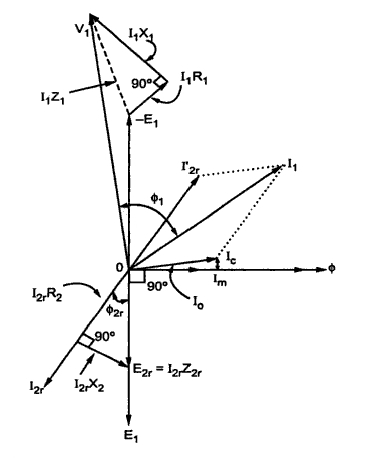
Transformer Loading and On-load Phasor Diagrams

PHASOR DIAGRAM ( INDUCTIVE LOAD) FOR A SINGLE PHASE TRANSFORMER - YouTube
Transformer ON Load Condition - Phasor Diagram & Operation

9.17. Draw and explain phasor diagram for voltageand current in a

Transformer with lagging Power Factor Load | Phasor Diagram for
